Charles Thomas

Aspiring Theoretical Physicist
Basic Quantum Computing - Multi Qubit Systems
by Charles Thomas
Last time, we talked about single qubit gates, but to do anything really interesting we need to make use of multiple qubits.
Describing Multi Qubit Systems
Before we talk about gates acting on multiple qubits, we need to talk about describing systems of multiple qubits.
When we had 1 qubit, there were only two possible outcomes when we measured a qubit: 0 and 1. So we used two ket vectors to describe a qubit:
\[\ket{0} \text{ and }\ket{1}\]Now if I have two qubits, then when I measure the system, I could get four outcomes: 00, 01, 10 and 11. So I need to use 4 ket vectors to describe a two-qubit system:
\[\ket{00},\ket{01},\ket{10} \text{ and }\ket{11}\]Notation
So in general I can write a two-qubit system as:
\[a\ket{00} + b\ket{01} + c\ket{10} + d\ket{11}\]We can now extend this to 3 qubits:
\[a\ket{000} + b\ket{001} + c\ket{010} + d\ket{011} + e\ket{100} + f\ket{101} + g\ket{110} + h\ket{111}\]In fact, we can describe a system of n qubits in this way, we just keep adding kets.
Let’s return to the two-qubit system and quickly talk about notation. We originally wrote the two-qubit system as:
\[a\ket{00} + b\ket{01} + c\ket{10} + d\ket{11}\]But you might also see it written as:
\[a\ket{0}_A\ket{0}_B + b\ket{0}_A\ket{1}_B + c\ket{1}_A\ket{0}_B + d\ket{1}_A\ket{1}_B\]when we want to make it obvious which of the two qubits is which.
Or even as:
\[a(\ket{0}\otimes\ket{0}) + b(\ket{0}\otimes\ket{1}) + c(\ket{1}\otimes\ket{0}) + d(\ket{1}\otimes\ket{1})\]These all mean the same thing but just are different ways of writing it down.
We can also use the column vector syntax to describe a two-qubit system. Now since we have 4 kets we need to have 4 entries. So
\[a\ket{00} + b\ket{01} + c\ket{10} + d\ket{11}\]becomes
\[\begin{bmatrix}a \\ b \\ c \\d\end{bmatrix}\]Swap Gates
Now, we can talk about some simple gates for two-qubit systems. One of the most simple gates is the SWAP gate. This gate swaps two qubits so it takes:
\[a\ket{0}_A\ket{0}_B + b\ket{0}_A\ket{1}_B + c\ket{1}_A\ket{0}_B + d\ket{1}_A\ket{1}_B\]And sends it to:
\[a\ket{0}_B\ket{0}_A + b\ket{0}_B\ket{1}_A + c\ket{1}_B\ket{0}_A + d\ket{1}_B\ket{1}_A\]which we can rewrite as:
\[a\ket{0}_A\ket{0}_B + c\ket{0}_A\ket{1}_B + b\ket{1}_A\ket{0}_B + d\ket{1}_A\ket{1}_B\]We can represent this using the following matrix:
\[\begin{bmatrix} 1 & 0 & 0 & 0\\ 0 & 0 & 1 & 0\\ 0 & 1 & 0 & 0\\ 0 & 0 & 0 & 1\\ \end{bmatrix}\]And we’ll use the following symbol:

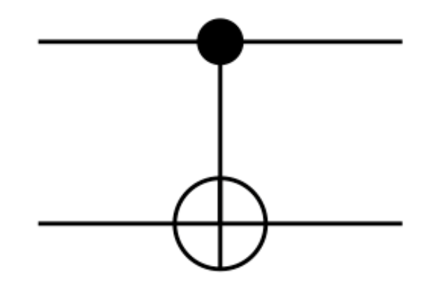
Controlled Gates
Now we have two qubits, it would be nice if we could do some logic, where a gate only has an effect if another qubit is in a particular state. We can do this with the concept of controlled gates.
To get to grips with this, we’ll work through an example: the CNOT gate. The CNOT gate or controlled not gate takes in two qubits: a control qubit and a target qubit. If the control qubit is 1 then it applies a NOT gate to the target qubit.
So let’s consider the simple system:
\[a\ket{0}_C\ket{0}_T\]where C represents the control qubit and T represents the target qubit.
Since the control qubit is 0 the CNOT gate does not change this state. But if we consider
\[a\ket{1}_C\ket{0}_T\]Since the control qubit is 1 it will change the target qubit to 1 so we get:
\[a\ket{1}_C\ket{1}_T\]We can put this all together for a general two-qubit system. So if I have:
\[a\ket{0}_C\ket{0}_T + b\ket{0}_C\ket{1}_T + c\ket{1}_C\ket{0}_T + d\ket{1}_C\ket{1}_T\]Then a CNOT gate will flip the target qubit where the control qubit is 1. So we get:
\[a\ket{0}_C\ket{0}_T + b\ket{0}_C\ket{1}_T + c\ket{1}_C\ket{1}_T + d\ket{1}_C\ket{0}_T\] \[=a\ket{0}_C\ket{0}_T + b\ket{0}_C\ket{1}_T + d\ket{1}_C\ket{0}_T + c\ket{1}_C\ket{1}_T\]So we can represent the CNOT gate with the following matrix:
\[\begin{bmatrix} 1 & 0 & 0 & 0\\ 0 & 1 & 0 & 0\\ 0 & 0 & 0 & 1\\ 0 & 0 & 1 & 0\\ \end{bmatrix}\]We use the following symbol:
We can take this idea of a controlled gate and apply it to other gates that we’ve seen e.g. we could make a controlled Y gate that only applies a Y gate if the control qubit is 1.
Single Qubit Gates on Multi Qubit Systems
Finally, let’s talk about how we can use the single-qubit gates we learned about last time in our multi-qubit system.
Let’s take our Hadamard gate from last time which did the following:
\[\ket{0} \to \frac{\ket{0} + \ket{1}}{\sqrt{2}}\] \[\ket{1} \to \frac{\ket{0} - \ket{1}}{\sqrt{2}}\]Now, if we have a two-qubit system:
\[a\ket{0}_A\ket{0}_B + b\ket{0}_A\ket{1}_B + c\ket{1}_A\ket{0}_B + d\ket{1}_A\ket{1}_B\]Let’s imagine what happens when we apply the Hadamard gate just to the A qubit. Let’s start by doing the substitution from above:
\[a(\frac{\ket{0}_A + \ket{1}_A}{\sqrt{2}})\ket{0}_B + b(\frac{\ket{0}_A + \ket{1}_A}{\sqrt{2}})\ket{1}_B + c(\frac{\ket{0}_A - \ket{1}_A}{\sqrt{2}})\ket{0}_B + d(\frac{\ket{0}_A - \ket{1}_A}{\sqrt{2}})\ket{1}_B\]Now we can simply this to:
\[\frac{(a+c)}{\sqrt{2}}\ket{0}_A\ket{0}_B + \frac{(b+d)}{\sqrt{2}}\ket{0}_A\ket{1}_B + \frac{(a-c)}{\sqrt{2}}\ket{1}_A\ket{0}_B + \frac{(b-d)}{\sqrt{2}}\ket{1}_A\ket{1}_B\]So this is the output of applying a Hadamard gate to one qubit in a two-qubit system. All we had to do was act on the first qubit.
Now how do we represent this as a matrix.
We’ll let’s start by representing it by what we want to do as:
\[H_A \otimes I_B\]What this means is that we want to apply a Hadamard Gate to the first qubit and the identity gate e.g. the fate that does nothing to the second qubit.
Now let’s replace these symbols by the matching single qubit matrices:
\[\frac{1}{\sqrt{2}}\begin{bmatrix}1 & 1 \\ 1 & -1\end{bmatrix} \otimes \begin{bmatrix}1 & 0 \\ 0 & 1\end{bmatrix}\]Now this is called the tensor product of two matrices and there is a formula for evaluating it given by:
\[\begin{bmatrix}a & b \\ c & d\end{bmatrix} \otimes \begin{bmatrix}e & f \\ g & h\end{bmatrix} = \begin{bmatrix}a \begin{bmatrix}e & f \\ g & h\end{bmatrix} & b \begin{bmatrix}e & f \\ g & h\end{bmatrix} \\ c \begin{bmatrix}e & f \\ g & h\end{bmatrix} & d \begin{bmatrix}e & f \\ g & h\end{bmatrix}\end{bmatrix}=\begin{bmatrix}ae & af & be & bf \\ag & ah & bg & bh \\ ce & cf & de & df \\ cg & ch & dg & dh \end{bmatrix}\]which in our case will give us:
\[\frac{1}{\sqrt{2}} \begin{bmatrix}1 \begin{bmatrix}1 & 0 \\ 0 & 1\end{bmatrix} & 1 \begin{bmatrix}1 & 0 \\ 0 & 1\end{bmatrix} \\ 1 \begin{bmatrix}1 & 0 \\ 0 & 1\end{bmatrix} & -1 \begin{bmatrix}1 & 0 \\ 0 & 1\end{bmatrix} \end{bmatrix}\] \[=\frac{1}{\sqrt{2}} \begin{bmatrix} 1 & 0 & 1 & 0 \\ 0 & 1 & 0 & 1 \\ 1 & 0 & -1 & 0 \\ 0 & 1 & 0 & -1 \end{bmatrix}\]Now we can use this formula to apply any single qubit gate to a two-qubit system. So if I wanted to apply a Y gate to the second qubit I would write:
\[I_A \otimes Y_B\]Then substitute in the matrices and apply the formula
tags: